MOZA Pit House Software
MOZA Pit House User Manual
目录
- 1. Installation
- 2. Main page
- 3. configuration page of the Base
- 3.3.1 One-key setting mode
- 3.3.2 Loading presets
- 3.3.3 Export preset
- 3.3.4 Save as one-click settings
- 4. Steering wheel configuration page
- 5. Pedal configuration page
- 6. Dashboard configuration page
- 7. Firmware upgrade page
- 8. System setting page
- 9. Maintenance tools
1. Installation
The software provides two installation packages, one is an offline installation package and the other is an online installation package. Whether online or offline, the content of the installed program is the same. Users can choose one of the two installation packages according to the characteristics of the two installation packages and their own needs.
1.1. Offline installation package
It is convenient to install offline packages without the internet, which is suitable for an environment with weak network signals. The disadvantage is that it’s large, and it may not be the latest version after offline installation which needs to be updated online.
1.2. Online installation package
The online installation document is small, which ensures that the installed programs are up to date. The disadvantage is that it needs to be connected to the Internet, and the program cannot be installed when the network is disconnected.
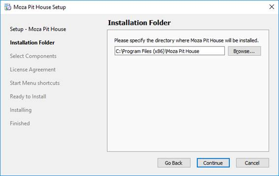
1.3. Installation process
The installer will install in C: \ program files (x86) \ MOZA pit house directory by default. The user can manually change and select another directory.
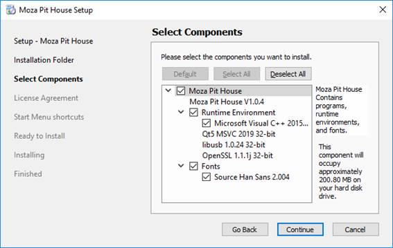
After determining the installation directory, enter an important step: Select the installation component. The component is divided into three parts: program, program operating environment, and font library.
The Moza pit house program is required. Only Microsoft Visual C + + 2015-2019 redistributable (x86) and source Han Sans 2.004 Siyuan font library are available. Users choose to download one according to their own needs. The purpose of installing the Siyuan font library is to beautify the program. Microsoft Visual C + + 2015 – 2019 redistributable (x86) is an important component. If the user’s computer does not have this component and does not choose to install it, the program will not run. In order to make the program run normally and the user is not sure whether the component is installed on their computer, it is recommended to select and install the component.
After selecting the components, users need to read and confirm the license agreement of the software. Users need to accept a license to install and use the software. The detailed protocol can be read by users during installation. This note does not make too many statements.

The installation starts when you accept the license.

Figure 1.3-4 during installation 
figure 1.3-5 installation completed
After installation, you will be asked whether to install Microsoft Visual C + + 2015-2019 redistributable (x86) component or not. If the user does not check to install this component, ignore it.
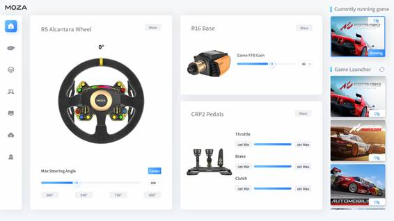
2. Main page
The main page is divided into two parts: game list and quick configuration. The quick configuration can read and configure some parameters of the base, steering wheel, and pedal equipment. The functions of the game list include whether the game is installed, the configuration of game telemetry data, and the startup of the game.
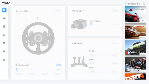
If the device is connected successfully, the picture of the device is in color, and the device parameters can be configured. If the device is disconnected, the configuration function will not be available and the background of the picture will be gray.
2.1. Game start
The software can start the game in two ways: Steam starts the game, and the custom path starts the game.
When steam starts the game mode, the software will search whether the game is installed on the computer. If the software does not find the game on the user’s computer, the “not installed” label in gray will be displayed on the cover of the game. Users can start the game through steam software. Starting the game in this way is exactly the same as the way users start the game in Steam.

Figure 1.1-1 Not installed this game 
Figure 1.1-2 Steam Launch Game Mode
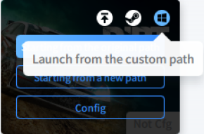
In the custom path startup game mode, the “not installed” label will not appear on the game cover. This mode is generally used to start non-Steam games. When the software is started, the software will automatically obtain the game path installed in the user’s computer, without the user setting the game path. If the computer gets the wrong path, the user can reset the path.
2.2. Game configuration
The game configuration function is to configure the telemetry data of the game. After the successful configuration, the software can obtain the telemetry data of the game, the dashboard can display the game data, and the steering wheel can correctly flash the speed indicator. It can be configured in steam startup mode and custom mode.

Figure 1.2-1 configuration under custom startup mode 
figure 1.2-2 configuration under steam startup mode
After configured successfully, the “configured” label in the blue font will appear on the game cover. The configuration button will be hidden.

Figure 1.2-3 game cover display configured figure 
figure 1.2-4 configuration button hidden
When the configuration fails, the following prompt will display:
Tip 1: unable to open the configuration file. The file may not exist! Try to enter the game before configuring.
When this prompt appears, the configuration file may have been deleted by the user by mistake or the configuration file has not been created yet. The user can try to enter the game first and let the game automatically create the profile. Note that the user is best to configure when the game is closed. Although the configuration may be successful when the game is running, it will not take effect. Because the configuration file configured by the software at this time is not recognized by the game. If the user clicks on the configuration while the game is running, just restart the game.

Tip 2: the game does not support the automatic configuration of telemetry data, please configure it manually after entering the game.
When this prompt appears, the software does not support the automatic configuration of the game temporarily. Users need to enter the game to configure telemetry data. It is expected that future versions will support the automatic configuration of the game.

Tip 3: file configuration failed, unknown error!
When this prompt appears, the system may be unresponsive or out of memory. Users can try to close some unrelated programs that are running or restart the computer for reconfiguration.
2.3. Quick configuration of steering wheel
The quick configuration of the steering wheel can set the maximum angle of the steering wheel and the centering of the steering wheel. It can read the corner of the steering wheel and the button test display of the steering wheel. To set more configurations, click the “more settings” button on the upper right to jump to the steering wheel configuration page.
Steering wheel centering is used for initial installation or when the steering wheel angle has deviated, it can be adjusted to normal. After setting the centering software, the current steering wheel steering angle is 0 °..
When the user rotates the steering wheel, the software will calculate the steering angle of the steering wheel and display it. The user can also set the maximum angle of the steering wheel. The maximum steering wheel angle is the steering value of the steering wheel from the leftmost to the rightmost.

Figure 1.3-1 effect after setting alignment figure 
1.3-2 effect after rotating 60 °
2.4. Quick configuration of base
The quick configuration of the pedestal can set the game force feedback intensity parameters of the base. To set more configurations, click the “more settings” button on the upper right to jump to the base configuration page.

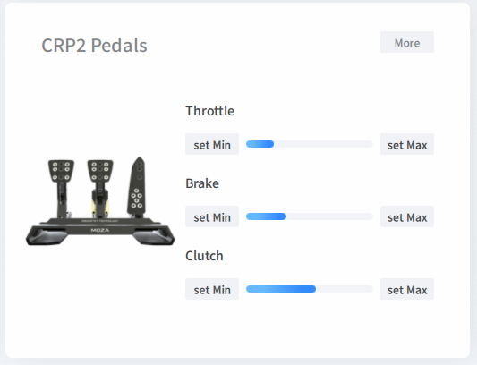
2.5. Pedal quick configuration
The pedal shortcut configuration can set the start and end parameters of the pedal, the start and end parameters of the brake, the start and end parameters of the clutch.
The start point or endpoint parameters can be set according to the angle of the current pedal. When a certain pedal is depressed, the start point (set Min) and endpoint (set Max) are set according to the depressed value. If you want to set more configurations, you can click the “More Settings” button on the upper right to jump to the pedal configuration page. The start point parameter cannot be greater than the endpoint parameter, and similarly, the endpoint parameter cannot be less than the start point parameter.
3. configuration page of the Base
The base configuration is divided into the basic setting, professional setting, and road perception equalizer.
3.1. Basic settings
It is sufficient for ordinary users to use the basic parameters.
Description of parameters included in basic settings:
a. Maximum steering angle: the maximum angle at which the steering wheel turns from the left limit to the right limit.
b. Game force filtering: by adjusting the parameters in the road perception equalizer, adjust the bandwidth of the low-pass filter to provide a more comfortable feel. When the parameters of the road perception equalizer are modified, the game force filter display will turn red, as shown in Figure 2.1. When the game force filter has been modified by the road perception equalizer parameters (in the red state), reconfiguring the game force filter will cover the road perception equalizer parameters. The game force filter parameters and road perception equalizer parameters affect each other.
c. Game force feedback intensity: adjust the overall intensity of the force feedback given in the game.
d. Mechanical force feedback strength: adjust the overall strength of the mechanical force feedback of the base motor. The mechanical force is the force simulated by the algorithm, which has nothing to do with the game force.
e. Maximum steering wheel speed limit: in order to protect the driver, the algorithm limits the steering wheel speed when the steering wheel exceeds the allowable maximum speed.
f. Mechanical centering strength: simulate a centering effect that is not affected by the game, and simulate the mechanical springs to centering the steering wheel.
g. Mechanical damping ratio: comprehensively adjust the mechanical damping force according to the mechanical return strength, mechanical force feedback strength, natural inertia, and game force feedback strength, which is convenient for ordinary users to adjust.
h. Auxiliary centering control: Turning on can suppress the rapid oscillation of the steering wheel and protect the driver.
The quick setting function is more convenient for ordinary users. The parameter modification relationship corresponds to the quick setting racing mode.
Table parameter modification relationship corresponding to quick setting racing mode2

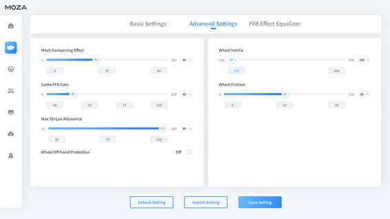
3.2. Specialty setting
Professional settings can set more advanced parameters, which are suitable for old players or racing drivers.
Description of parameters included in specialty settings:
a. Mechanical damping: simulate a damping force that is not affected by the game. The damping force increases linearly with the increase of steering wheel speed. The parameters of mechanical damping ratio and mechanical damping force affect each other. If you modify any parameter, the other parameter will change accordingly.
b. Game force feedback intensity: like the basic setting, the professional setting also has this parameter, but in the professional setting, the game force feedback intensity can be set up to twice.
c. Maximum output torque limit: allow the maximum output torque of the motor. Prevent damage caused by excessive force feedback. For users with lower hand strength, it is recommended to set this parameter smaller.
d. Hand-off protection: Turn on to detect that when the hand is off the steering wheel, the algorithm controls the steering wheel to remain in the neutral position. Prevent injuries caused by violent shaking. When the steering wheel is not connected, this parameter is invalid.
e. Natural inertia: the natural inertia simulates the steering wheel with different weights. In order to meet the real feeling, the user needs to manually adjust the mechanical damping and use it with this parameter. This parameter cannot be set when the steering wheel is not connected. Fixed at 100.
f. Mechanical friction: simulates a friction effect that is not affected by the game. It can be used to prevent oscillation or simulate the steering rack of a car without power steering.
3.3. One-click settings and preset library
The Base one-click setup is now linked to the preset library.The preset library is a library that manages multiple presets. The preset library directory path is "Documentation/MOZA Pit House/PresetLibrary".
Users can customize multiple presets, then store into this preset library, and use these presets in one-click settings to solve the problem of repeatedly adjusting parameters when playing different games, different models or different modes.

3.3.1 One-key setting mode
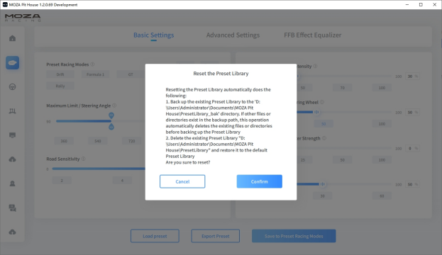
When you use it for the first time, a set of official presets will be automatically generated in the preset library, each preset contains basic settings, professional settings and parameters of road-aware equalizer. Users can choose the mode they need and make personalized modifications according to their personal needs.
It should be noted here that when we select a mode, the mouse can hover over the corresponding mode button, and a list of presets in this mode will appear above the button, and we can choose the preset we need (if there is only one, it is not support selection). Clicking the "Browse" button will launch the file explorer to browse the preset library directory.
Click the "Reset" button to reset the preset library. Although the reset process automatically backs up the preset library, the backup preset library is cleaned up on the next reset. Therefore, if there are presets that need to be kept, please move the presets from the backup preset library directory to a safe directory in time.
3.3.2 Loading presets
Under the base configuration page, click the "Load Preset" button, a file selection window will pop up, select and load the preset file into the current parameters of the base.
3.3.3 Export preset
Under the base configuration page, click the "Export Preset" button to export the current parameters of the base to the specified location.
3.3.4 Save as one-click settings
Under the base configuration page, click "Save as one-key settings", and the Save as one-key settings window will pop up.
Click the "Save" button to save the current parameters of the base as a preset and save it to the preset library, or overwrite the existing preset file in the preset library.

3.4. Road sense equalizer
The road perception equalizer can set the amplitude gain of game road conditions.
4. Steering wheel configuration page
There are four configurable parameters on the steering wheel configuration page:
a. Speed follow-up: turn on or off the relationship between steering wheel light and speed.
b. Speed prompt: the relationship between the current percentage of engine speed and the light on in the game.
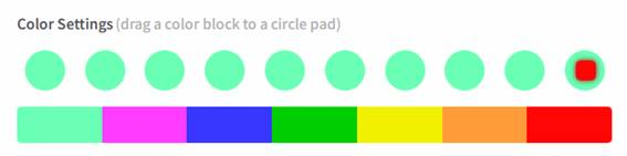
c. Color setting: sets the luminous color of each lamp from left to right.
d. Brightness adjustment: brightness of all lamps.

When the advance type is selected, the first light will be on when the speed percentage reaches 75%. When the speed percentage reaches 79%, the first and second lights will be on. As the speed percentage increases, the number of lights will increase. The relationship between the current engine speed percentage and the light on and the model type.
Table 3 Relationship between speed percentage and light on
To change the color of the light, press the mouse in the color square or other lights, and a small rectangle will appear at the mouse pointer. The color can be changed by moving the small rectangle to the lamp to be changed.
The steering wheel image on the configuration page not only displays the appearance of the current product but also detects that the user presses any key on the steering wheel. The steering wheel of the RS Alcantara disc model has a variety of buttons: horn, ordinary button, left and right rocker, left and right knobs, up and down paddles. When users interact with different buttons, different effects will be displayed on the software.

Fig. 3-3 effect of left and right knob buttons rotating respectively 
Fig. 3-4 effect of left and right knob buttons pressing

Fig. 3-5 effect of pressing ordinary button 
Fig. 3-6 effect of pressing the horn

Fig. 3-7 effect of pressing the paddle 
Fig. 3-8 effect of pressing the rocker
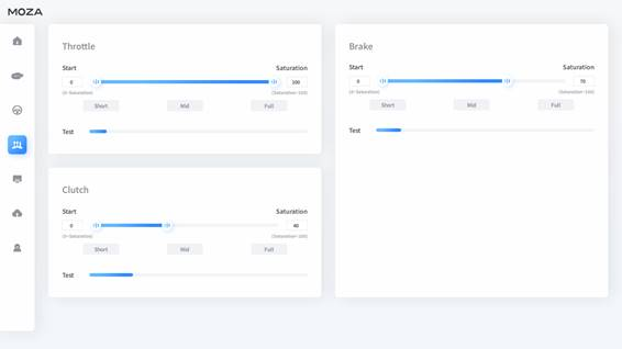
5. Pedal configuration page
The pedal configuration page can configure accelerator start and end parameters, brake start and end parameters, clutch start, and end parameters. In addition to the configuration parameters, it can also detect the angle value of the pedal is pressed.
Accelerator, brake, and clutch all have quick travel settings. Only endpoint parameters are set for short stroke, long-stroke, and full stroke, and the set parameter values are 40, 70, and 100 respectively.
6. Dashboard configuration page
At present, there are only two configurable parameters on the dashboard configuration page: screen brightness and dashboard display style. Different styles display different game data. The following images show the style of dashboard-style of the qualifying Version.

7. Firmware upgrade page
The firmware upgrade page can only be used when the device is connected. If the device is not connected, the device cannot be upgraded.
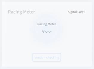
When the device is connected normally, the latest firmware version can be obtained by checking the update button. After checking the update, if a new version is found, the firmware can be updated.

Figure 6-2 status in version check Figure 
6-3 is the latest version status

Figure 6-4 updatable status 
figure 6-5 upgrading status

Figure 6-6 successful upgrade 
figure 6-7 failed upgrade
When the upgrade fails, you need to retry until the upgrade succeeds. If the upgrade fails multiple times, there may be a hardware error. It needs to be repaired at the maintenance point.
8. System setting page
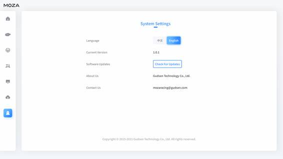
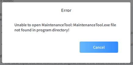
The software version can be viewed on the system settings page. It can detect whether there is the latest version. If a new version is detected, an update prompt window will appear. If you click Update installation, the software will close and open the maintenance tool: maintainancetool.exe to update.

Two files are required to run the maintenance tool: maintainancetool.dat and installer.dat.The user cannot change it at will, otherwise, the maintenance tool will not be able to run and upgrade the software. If the user deletes it by mistake, please reinstall the program.


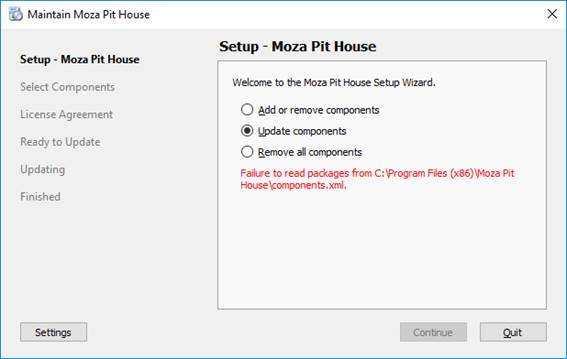
9. Maintenance tools
The software has a maintenance tool to manage the addition, deletion, update and uninstall of the software program. The maintenance tool will be generated with the installation package.
9.1. Add or remove components
Use this option when installing the program, some components are not checked or removed some components. For example, Siyuan font library, if the user does not install the font library during installation, you can add and install the font library again here.
9.2. Update components
When the software detects a new version, the user needs to select this option to upgrade the software.
9.3. Unload all
Removing all components will completely delete all information.

9.4. Precautions
A components.xml is required for the use of the maintenance tool. Do not modify it, otherwise, the maintenance tool will not work normally. The file is created during installation. If the user mistakenly deletes it, just reinstall the program.
Was this article helpful?
That’s Great!
Thank you for your feedback
Sorry! We couldn't be helpful
Thank you for your feedback
Feedback sent
We appreciate your effort and will try to fix the article